SERVICE MANUAL
Legend for Fig. 23
1
Outlet Port
2
Spring
3
Cap, Top
4
Screw, Cap 3/8"-16x1"
5
Cup, Filter
6
Strainer
7
Nut, 3/8"-16
8
Washer, Lock 3/8"-ext. tooth
9
Nut, 3/8"-16
10
Rod, Support
11
Washer, Lock 3/8"-ext. tooth
12
Nut, 3/8"-16
13
Screw, Cap Socket hd. 3/8"-16x1l"
14
Gasket
15
Spindle
16
Seat, Ring
17
Heater
18
Thermostat
19
Spring
20
Port, Exhaust
21
Ring, Retaining
22
Spring
23
Cup, U
24
Ring, O
25
Piston
26
Port (UNL) Unloader
27
Nut, Unloader
28
Sleeve
29
Cap, Bottom
30
Gasket
31
Gasket
32
Plate, Support
33
Body
34
Deflector
35
Washer
36
Ring, Packing
37
Spring, V
38
Filter
39
Spring
40
Gasket
41
Valve, Safety
42
Spindle
43
Gasket
44
Nut
5.
Remove complete unloader valve assembly
including copper gaskets (10).
Excessive accumulation of oil in the unloader assembly
indicates that the air compressor requires attention.
6.
Examine unloader valve assembly. If the
unloader sleeve (5) is nicked, wrinkled or has axial
scratches, the unloader valve assembly should be
replaced. The unloader valve assembly if clogged should
be cleaned with a good cleansing solvent.
7.
Do not remove retaining ring (7) from unloader
spindle (9) since they are serviced as an assembly with
spring (8) and seat ring (1).
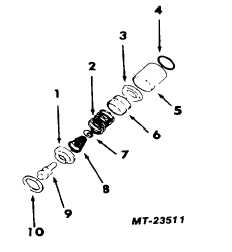
Fig. 24 Contents of Unloader Valve Kit
1
Ring Seat
6Piston
2
Spring, Large
7Ring, Retaining
3
Cup, U
8Spring, Small
4
Ring, 0
9Spindle, Unloader
5
Sleeve
10Gasket (2 Req’d.)
8.
Install new "U" cup (3) in groove of unloader
piston. Lips of "U" cup should face away from
spring seat. Do not use sharp tools that may mar
or score parts.
9.
Apply a light film of Item 1 in LUBRICANT
SPECIFICATIONS to O-ring (4) and position on
unloader nut.
10.
Position the two copper gaskets (10) together
and lightly coat exposed surfaces with Item 1 of
LUBRICANT SPECIFICATIONS. Then position
lubricated gaskets on shoulder of ring seat (1).
Gaskets should be on face opposite the spring
(8).
11.
Place gaskets (10) followed by seat ring as-
sembly into bottom cap (Item 29 of Fig. 23).
12.
Install unloader sleeve (5) in unloader port
against the seat ring. Be sure the 12.7 mm (I")
diameter cross hole is next to the seat ring.
13.
Position large spring (2) in the sleeve (5) with
large diameter coil against seat ring.
14.
Insert unloader piston (6) into unloader sleeve.
Lips of U-cup (3) must face out with spring seat
toward spring. The unloader spindle (9) and seat
ring (1) is a mated assembly and should not be
disassembled. If either the ring seat or spindle is
nicked, the entire mated assembly must be
replaced as an assembly.
CTS-4079 - CHAPTER XIV - Page 15