SERVICE MANUAL
8.
Wash all remaining parts in a commercial
solvent making sure all surfaces, bores, ports
and
passages
are
clean
and
dry
before
reassembly.
The heater and thermostat assembly in the AD-2
end cover are non-serviceable. Do not remove
the thermostat cover. Should this assembly
become defective, the end cover must be
replaced.
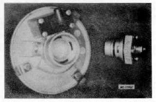
Fig. 18 AD-2 End Cover Assembly with
Purge Valve Assembly Removed
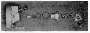
Fig. 19 Purge Valve Assembly Disassembled
Reassembly
1.
Lubricate the piston O-ring and install it on the
piston.
2.
Lubricate the piston bore and install the piston.
3.
Install the purge piston return spring and
piston.
4.
Install the purge valve in the large cap nut so
that the rubber portion rests on the metal seat of
the cap nut.
5.
Secure the valve to the piston using the 1/4"-20
capscrew and lockwasher and torque to 5.5 N.m
(50 in. lbs.).
6.
Lubricate and install the two cap nut 0- rings.
7.
Lubricate the cap nut threads and the cap nut
bore of the end cover and install the cap nut;
torque it to 19.8-27.5 N.m (180- 250 in. lbs.).
8.
Secure the exhaust diaphragm to the exhaust
cover using the No. 6-32 phillips head screw and
diaphragm washer.
9.
Secure the exhaust cover to the purge valve hex
head cap nut using the No. 6-32 phillips head
screws.
10.
Lubricate and install the large diameter 0- ring
around the end cover assembly.
OUTLET PORT CHECK VALVE ON AD-2
The one-way check valve located in the outlet port of
the AD-2 dryer assembly is replaced as a complete
assembly. The removal and installation procedure is as
follows (Refer to Fig.
20).
1.
Set parking brake by applying the control valve.
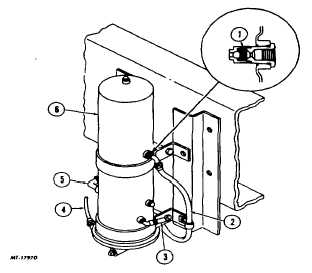
Fig. 20 Typical Air Dryer Installation
1
Check Valve Assy.
2
Supply to Air Reservoir
3
Pressure Relief Valve
4
Governor Control Line
5
Air Source From Compressor
6
Air Dryer Assembly
CTS - 4079 - CHAPTER XIV - Page 11