SERVICE MANUAL
2.
Remove the ball check valve retaining clip and
remove and discard the rubber ball valve.
3.
Clean the desiccant plate thoroughly using a
quality commercial solvent making sure the
purge orifice and check valve seat are clean.
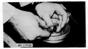
4.
Install new ball check valve and replace the
retaining clip and screw (Fig. 7).
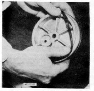
5.
Thoroughly lubricate the two new o-rings and
install them in their respective grooves in the
purge plate (Fig. 8).
6.
Set the desiccant sealing plate aside for
reinstallation on the desiccant cartridge.
Fig. 7 Installing Check Valve
REPLACING DESICCANT CARTRIDGE
If the desiccant cartridge is to be replaced as an
assembly rather than rebuilt (see desiccant cartridge
rebuilding instructions), the cartridge removed from the
air dryer may be discarded after the desiccant sealing
plate is removed.
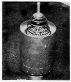
The current revision replacement desiccant cartridge
is shown in Fig. 9. All prior revisions of the cartridge will
interchange with no modifications to either air dryer.
Prior to installing the new replacement cartridge in
the air dryer, the following steps must be as follows:
1.
Carefully remove the lock nut from the cartridge
bolt using an 11/16" open end or box wrench.
Care must be taken not to allow the cartridge
bolt to slip out of the cartridge when the lock nut
is removed. Loss of desiccant material will occur
should this happen.
2.
Install the previously rebuilt desiccant sealing
plate on the cartridge bolt so that the ball check
retaining clip remains visible (see Fig. 7).
3.
While holding the cartridge bolt, reinstall the lock
nut on the cartridge bolt.
Fig. 8 Installing O-Rings
Fig. 9 Replacement Desiccant Cartridge
IMPORTANT
Before tightening the lock nut down,
make
certain
that
the
shoulder
(unthreaded portion) of the cartridge bolt
extends slightly above the perforated
desiccant plate (see Fig. 14).
CTS-4079 - CHAPTER XIV - Page 7