SERVICE MANUAL
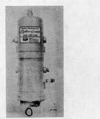
Fig. 1 AD-1 Air Dryer
BENDIX AD1 & AD2 TYPES
DESCRIPTION
The air dryer function is to collect and remove
moisture and contaminants before air reaches the first
reservoir, thus providing "super dry" air for the air brake
system. Daily draining of the air system reservoirs is no
longer necessary with an air dryer and air brake system
maintenance is considerably reduced when compared to
an air brake system without an air dryer.
The air dryer is installed in the discharge line
between the air compressor and supply reservoir. The
unit is mounted vertically, usually on the frame of the
vehicle.
The housing assembly consists of two cylindrical
steel stampings welded together. The housing on the
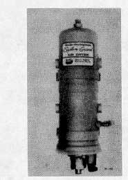
AD-2 Air Dryer incorporates two inlet ports, one reservoir
port and one purge volume port. The side outlet port of
the AD-2 has an integral single check valve with the top
port used for the addition of purge volume.
The AD-1 Air Dryer has two inlet and three outlet
ports, but is not equipped with a single check valve in
any of the three outlet ports.
The safety valve protects against excessive pressure
build-up within the housing.
The desiccant sealing plate is located midway in the
housing assembly and houses a replaceable single type
check ball and a purge orifice. The desiccant cartridge
and paper pleated oil filter are removable and com-
Fig. 2 AD-2 Air Dryer
prise a complete serviceable unit.
The desiccant beads, referred to as the "drying bed,"
are a drying substance which has the unique property of
exposing a tremendous surface area in proportion to its
bulk. Desiccant beads weighing .454 kg. (1 lb.) have
about 186,000 m2 (two million square feet) of absorptive
area made up of a large number of submiscroscopic
cavities in each bead. Each bead absorbs or extracts
moisture from the compressed air.
The desiccant beads are held in place in the
cartridge with steel perforated plates and filter cloths.
The top plate is held in place by a spring, while the
bottom plate rests on a shoulder about 3 mm (1/8") from
the bottom of cartridge housing.
The end cover assembly is retained by a lock
(retaining) ring, capscrews and retainers, and houses the
purge valve and heater assembly if so equipped.
The heater and thermostat assembly prevent freeze-
up in the purge drain valve when the dryer is used in
severe winter conditions. The heater and thermostat
assembly is standard in the AD-2 and was optional
equipment for the AD-1. The 60 watt, 12 or 24 volt DC
heater and thermostat assembly has an operating range
between 100 C and 320 C (500 F and 85 F).
OPERATION
The operation of the air dryer can best be described
by separating the operation into two cycles; the charge
cycle and the purge cycle.
CTS-4079 - CHAPTER XIV - Page 3


