SERVICE MANUAL
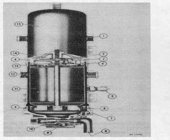
Fig. 3 Sectional View of AD-1 Air Dryer
1.
Outlet
2.
Nut
3.
Check Valve
4.
“O” Ring
5.
Safety Valve
6.
Oil filter
7.
Retaining Ring
8.
Exhaust Deflector
9.
Heater
10.
Purge Valve
11.
Desiccant
12.
Inlet
13.
Purge Orifice
14.
Jam Nut
15.
Purge Volume
Charge Cycle (Fig. 5)
With the compressor in its "loaded" or compressing
cycle, air from the compressor enters the air dryer
through the discharge line. When the air along with the
water and contaminants enter the air dryer, the velocity
or speed of the air reduces substantially and much of the
entrained liquid drops to the bottom or sump of the air
dryer. The initial air flow is toward the bottom of the
dryer, but air flow direction changes 180 degrees at the
bottom of the air dryer dropping some water and oil.
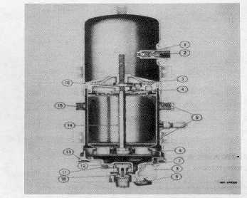
Fig. 4 Sectional View of AD-2 Air Dryer
1.
Check Valve
2.
Outlet
3.
Lock Nut
4.
Spring Retainer
5.
Perforated Plate
6.
Oil Filter
7.
Heater
8.
Thermostat Enclosure
9.
Electrical Terminal
10.
Purge Valve
11.
Control Port
12.
Purge Valve Piston
13.
Retaining Ring
14.
Cartridge Bolt
15.
Inlet
16.
Desiccant Sealing Plate
The air now passes through the oil filter which removes
some oil and foreign material but does not remove water
vapor. At this point, the air remains saturated with water.
The filtered air and vapors penetrate the desiccant drying
bed and the adsorption process begins. Water vapor is
removed from the air by the desiccant.
CTS-4079 - CHAPTER XIV - Page 4