SERVICE MANUAL
15.
Insert a 12.7 mm (i") diameter rod or equivalent
through the exhaust port in the bottom cap (Item
29 of Fig. 23) and into the cross hole of sleeve
(5) to maintain alignment. If the cross holes are
not aligned, the unit will not operate.
16.
Apply a non-hardening sealing compound to
thread of the unloader valve nut (Item 27 of Fig.
23) and install the nut. Tighten nut to 81 Nm (60
ft. lbs.) maintaining the alignment of the cross
holes of sleeve (5). Overtightening of the
unloader nut will result in damage to the
unloader assembly.
17.
Remove the alignment rod inserted in step 15.
18.
Reinstall the governor control line to UNL port in
center of unloader nut.
19.
Reinstall in air input line from the air com-
pressor.
20.
Connect electrical lead for the heater.
21.
Test
unit
using
the
instructions
listed
in
SERVICE CHECKS.
Servicing Deflector Assembly
There are several indications which may mean
that the deflector assembly needs servicing:
Compressed air was cooled by the unit but no
longer is cooled properly.
Water exhausted by the CR BRAKEMASTER is
brownish or brown particles are exhausted.
A piece of the deflector is caught in the unloader
valve assembly causing it not to operate
properly.
These situations can be caused by several
conditions. Check the TROUBLE SHOOTING GUIDE to
make sure that the probable cause is a malfunctioning
deflector assembly. If it is a malfunctioning deflector
assembly, the following are the instructions for replacing
this deflector assembly.
Refer to Fig. 25 for numbers in parenthesis.
1.
Refer to General Instructions.
2.
Disconnect air compressor service line at inlet
port.
3.
Disconnect governor control line from unloader
nut (Item 27 of Fig. 23).
4.
Disconnect wire from heater assembly.
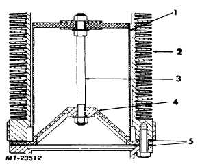
Fig. 25 Contents of Deflector Kit
1
Deflector
2
Body Tube
3
Rod, Support Assy. (Refer to
4
Plate, Mounting
5
Gaskets
5.
Remove the eight cap screws (Item 13 of Fig.
23) retaining bottom cap to body (2).
6.
Remove bottom cap and deflector assembly.
On older units the deflector is secured to the bottom cap.
If this is the case, the deflector should be
removed from the bottom cap by means of
removing the four screws holding the deflector to
the bottom cap. The feet of the bottom cap (to
which the deflector was attached) must be
removed.
7.
Remove all traces of old gasket(s) material from
gasket surfaces of bottom cap and body.
Discard old gaskets. Be careful not to scratch or
mar gasket surfaces.
8.
Wash bottom cap and inside of unit with
cleaning solvent.
9.
Position new gasket (5) on top of surface of
deflector mounting plate (4).
10.
Position second new gasket (5) on gasket
surface of bottom cap.
11.
Align bolt holes and position assembly against
bottom gasket surface of body tube (2). Use of
gasket sealant is NOT recommended.
CTS-4079 - CHAPTER XIV - Page 16