SERVICE MANUAL
12.
Insert eight cap screws to attach bottom cap to
body tube and deflector assembly. Tighten
alternately and evenly to 20.3 Nm (15 ft. lbs.). If
unit previously had old style deflector attached to
bottom cap, use the eight longer cap screws
contained in the deflector replacement kit.
13.
Reconnect the air line to the inlet port (this line
leads from the compressor service port).
14.
Reconnect the governor control line to the
unloader port in unloader nut (Item 27 of Fig.
23).
15.
Reconnect the wire to the heater.
16.
Test the unit following the instructions listed in
SERVICE CHECKS.
Servicing Check Valve Assembly
There are several indications which may mean
that the check valve needs servicing:
Air is exhausted from exhaust port when
compressor is in stand-by mode.
System air pressure bleeds off rapidly when air
using equipment is not being operated.
Compressor goes into stand by mode but cycles
rapidly.
Compressor attempts to build pressure but
system pressure will not build up.
Safety valve opens.
These situations can be caused by several
conditions. Check ’the TROUBLE SHOOTING GUIDE to
make sure that the probable cause is a defective
assembly. The following is the procedure for servicing
and replacing the check valve assembly.
Refer to Fig. 26 for numbers in parenthesis.
1.
Refer to the General Instructions.
2.
Disconnect air line at outlet port at top of unit.
3.
Remove top nut (4). This nut is spring loaded.
4.
Remove copper gaskets (3), spring (1), and
check valve spindle (2).
5.
Clean and dry entire check valve area and top
nut (4).
6.
Position new check valve spindle (2) in top cap
with tapered end down.
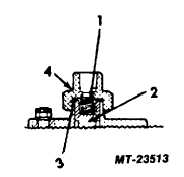
Fig. 26 Check Valve Assembly
1
Spring
3
Gaskets
2
Spindle
4
Nut
7.
Install spring (1) in check valve spindle.
8.
Position new copper gaskets (3) in nut (4) and
rub a small quantity of grease on the gaskets to
help them keep their position in the top nut.
9.
Thread nut on to top cap and torque to 81 Nm
(60 ft. lbs.). Top nut (4) is not included in check
valve replacement kit.
10.
Reconnect the air line to the outlet port. The
safety valve (Item 41 of Fig. 23) cannot be
serviced and it is recommended that it not be
removed from the top cap. If the safety valve
was removed, apply non-hardening sealant to
threads of top cap.
11.
Test the unit following the instructions listed in
SERVICE CHECKS.
Servicing Filter Assembly
Although the filter assembly of the unit is
designed to require little or no servicing, it is a good
practice to service the filter assembly when performing
service on the other filters located on the vehicle. This
servicing can be accomplished in one of two ways, either
replacing the entire filter assembly, or by servicing the
filter assembly. In most cases, simply servicing will only
be necessary. The following are the steps for servicing
the filter assembly. If the entire filter assembly is being
replaced, those steps preceded by an asterisk (*) can be
eliminated.
Refer to Fig. 27 for numbers in parenthesis.
1.
Refer to the General Instructions.
2.
Remove air line at outlet port.
CTS-4079 - CHAPTER XIV - Page 17