SERVICE MANUAL
3.
Remove eight cap screws holding top cap (2) to
body (8).
CAUTION
Use care in removing top cap bolts to
prevent bodily injury because the cap is
spring loaded with approximately 178
Nm (40 ft. lbs.).
4.
Remove spring (Item 39 in Fig. 23).
5.
Remove all traces of gasket material from top
cap and body gasket surfaces (2 & 7). Discard
gasket. Be careful not to scratch or score
gasket surfaces and wash top cap in cleaning
solvent.
6.
Remove complete filter assembly.
7.
Remove rubber packing ring (7) and discard.
8.
Discard old stainless steel filter. If you are
replacing entire filter assembly, the entire filter
assembly including filter cup (3), strainer (5) and
V-spring (4) may also be discarded.
9.
Wash strainer (5) and filter cup (3) in cleaning
solvent.
10.
Assemble stainless steel filter (6) in filter cup (3).
Filter should be stretched slightly to fill the space
in filter cup.
11.
Reinstall strainer (5) with flat face of strainer
towards stainless steel filter.
12.
Install V-spring (4) holding filter assembly
together.
13.
Install new packing ring (7) on ledge of body.
14.
Position filter assembly into body with large end
down. The filter must set on packing ring.
15.
Install heavy spring (39, Fig. 23) with larger
diameter coil against top of filter assembly.
16.
Position new gasket (1) on body. Do not use
gasket cement.
17.
Position top cap and spring so that the small
diameter coil on spring fits groove in top cap.
18.
Compress spring and install four 3/8 cap screws
(4, Fig. 23) into body. Each of these four (4)
screws should be engaged at least three full
turns before load on cap is removed. Cap
screws should be equally spaced. Then thread
remaining screws into place.
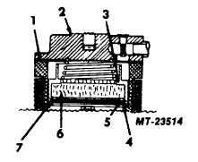
Fig. 27 Servicing Filter Assembly
1
Gasket
5
Strainer
2
Top Cap
6
Filter
3
Filter Cup
7
Packing Ring
4
V Spring
19.
Tighten all top cap bolts alternately and evenly to
20.4 Nm (15 ft. lbs.).
20.
Reconnect air line to outlet port.
21.
Test unit operation following instructions outlined
in SERVICE CHECKS.
Servicing
Thermostatically
Controlled
Cartridge
Type Heater
The current heat exchanger units contain a 12
volt 50 watt heater as standard equipment. This heater
requires a newly designed bottom cap which is
completely interchangeable with those in use previously.
Use of this new cap may, however, necessitate a change
of the deflector assembly if your present bottom cap has
the deflector attached to it by screws. Wrap around
strap type heaters, which are NOT thermostatically
controlled are available for this old style bottom cap.
Refer to Servicing Wrap-Around Strap Type Heater.
There are two kits used in servicing the
thermostatically
controlled
cartridge
type
heater
assembly. Both heaters are 50 watt, however, one is 12
volt and the other is a 24 volt.
Instructions for installing either of the kits are as
follows.
1.
Refer to the General Instructions.
2.
Disconnect the electrical line from the CR
BRAKEMASTER heater.
3.
Remove old cartridge type heater by loosening
set screw for heater on bottom cap.
4.
Remove old thermostat from bottom cap by
removing the two small screws which retain
CTS-4079 - CHAPTER XIV - Page 18