SERVICE MANUAL
DESCRIPTION
The
term
"foundation
brake"
is
given
to
those
components at wheels which actually do the braking.
This includes such items as brake shoes, lining, anchors,
drums and spider or backing plate. Although the slack
adjusters, cam and followers are not directly known as
components of the foundation brakes, they
will be covered herein.
MAINTENANCE
A regular schedule for periodic cleaning, lubrication,
adjustment and inspection should be established, usually
based on past experience and type of vehicle operation.
It is difficult to determine an exact maintenance interval
(time or mileage) since vehicles will be used in a wide
variety of operational applications and conditions.
To compensate for lining wear, brakes should be
adjusted frequently to maintain satisfactory operation and
efficient brakes.
Refer to BRAKE ADJUSTMENT for detailed adjustment
procedures.
Drain air reservoirs regularly as required. Local
conditions govern frequency. Dry climates require less
attention than humid areas, where it may be necessary
to drain reservoirs daily.
When draining air reservoirs, let all air bleed off and be
sure all drainage stops.
For details for the air system, refer to the appropriate air
brake system section.
BRAKE ADJUSTMENT
Brake adjustment can be a contributing factor of brake
complaints.
Proper
brake
adjustment
must
be
maintained. Do not overlook brake adjustment on the
trailer either. Brake balance on trucks and tractor trailers
is essential for good braking.
Periodic checking of push rod travel or brake adjustment
is essential for good braking. Push rod travel should be
checked every 6,000 km (4,000 miles) to determine if
adjustment is necessary. Push rod travel should be kept
at a minimum without brakes dragging.
Inspect brake lining every 19,000 km (12,000 miles) or
every 12 months, whichever occurs first. When brake
lining or blocks are worn to within 1.6 mn (1/16") of
rivets, brake lining must be replaced.
If brake lining is satisfactory, adjust brakes in the
following manner making brake adjustment, one wheel at
a time, with all drums in place and all slack adjusters
connected to chambers.
These instructions apply to manual adjustment type
slack adjusters.
1.
With wheels raised and parking brake released
so that wheels will rotate freely, check each
brake chamber push rod to make certain that it
is in fully released position. To do this,
disconnect push rod at slack adjuster. If push
rod moves toward (released) brake chamber,
turn worm shaft and rotate slack adjuster toward
push rod until clevis pin can be reinstalled.
2.
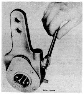
Disengage locking sleeve on worm shaft or
adjusting screw by depressing spring loaded
sleeve with a wrench (Fig. 1).
Fig. 1 illustrates the locking sleeve in its
disengaged position. Be sure sleeve is held in,
disengaging the adjusting screw when making
adjustments.
Use either an open or socket wrench when
making adjustment. Make certain locking sleeve
is held in, thereby disengaging the locking
mechanism. Never use a wrench on the sleeve
portion.
Fig. 1 SIack Adjuster Locking Sleeve on Adjusting Nut
CTS-4080W - Page 3