IV.STEERABLE DRIVE END DISASSEMBLY
D.
Spindle Yoke Removal
1.
Perform steps B and C, page 9 and page 10.
2.
Disconnect the steering rod by removing the
cotter pin, castle nut and then while prying
between the tie rod end and the tie rod arm,
sharply strike the side of the tie rod arm radially
to the tie rod end tapered stud. Disconnect the
brake hose.
3.
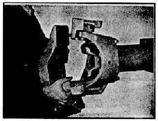
Remove four capscrews (See fig. 20)that retain
the universal joint cross and bearing to the outer
drive yoke.
4.
Support the spindle yoke while removing the four
capscrews at the upper kingpin bracket.
(See fig. 13.)
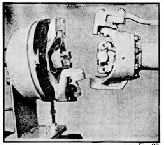
5.
Lower the spindle yoke and at the same time
rotate the top outward. (See fig. 21.) This
should allow the lower kingpin ball to come out
of its socket in the suspension yoke. The
spindle yoke can then be moved away from the
axle.
E.
Removal of the Outboard Section of the
Steerable Drive End
NOTE: After following this procedure, the outboard
section of the end may be disassembled on the
bench by following IV.B, C and D.
1.
Perform Items 1 and 2 of Step B, Page 9.
2.
Rotate the brake drum to position the outer drive
yoke horizontally.
3.Unbolt the universal joint cross and bearing from the
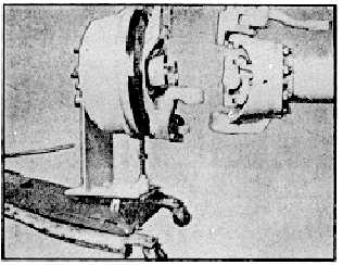
outer drive yoke. (See fig. 20.) 4. Attach the outboard
section of the steerable drive end to a transmission jack
that is equipped to handle the assembly. (See figs. 22
and 23.)
Fig. 21
Fig. 22
Fig. 23
-11-