IV. STEERABLE DRIVE END DISASSEMBLY
5.
Disconnect the steering tie rod by removing the
cotter pin, castle nut and then, while prying
between the tie rod end and the tie rod arm,
sharply strike the side of the tie rod arm radially
to the tie rod end tapered stud.
6.
Disconnect the brake hose.
7.
Remove the four bolts that hold the upper
kingpin bracket to the spindle yoke.
8.
Lower the transmission jack about two inches
and roll the outer section of the steerable drive
end away from the axle.
F.
Inner Axle Shaft Removal
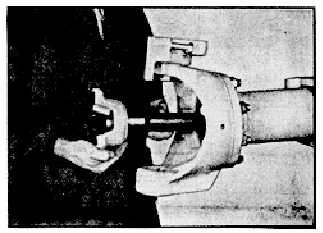
1.
Perform only step E above and then pull the axle
shaft and universal joint from the axle housing.
(See fig. 24.)
2.
Or after steps B, C, and D, pull the axle shaft
and universal joint from the axle.
G.
Lower Kingpin Bracket and Kingpin Removal
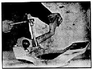
1.
The lower kingpin ball stud and the lower kingpin
bearing are exposed for inspection after steps B,
C, and D or after step E alone. (See fig. 25.)
Back off lower kingpin lock nut. Remove four
nuts and washers retaining the lower kingpin
bracket and tie rod arm to the spindle yoke. The
bracket may now be removed.
2.
A tool for rotating and holding the lower kingpin
ball stud may be made by welding a nut onto a
capscrew the head of which fits the socket in the
end of the lower kingpin ball stud. A standard
socket or wrench can then be used on the nut to
turn the capscrew and kingpin stud. An allen
wrench may be used.
3.
Screw the kingpin stud from the bracket.
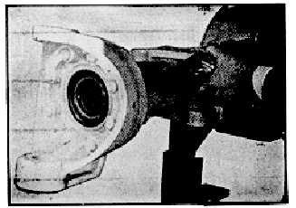
H.
Lower Kingpin Bearing Removal
After Section IV-E, and only if the bearing is
being replaced, drive the bearing out of the
suspension yoke by pushing on the lower kingpin
disc.
Fig. 24
Fig. 25
Fig. 26
-12-