IV. STEERABLE DRIVE END DISASSEMBLY
I.
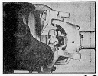
Upper Kingpin Removal
After Section IV-E, remove locknut from the
bottom of the upper kingpin. Use a jack or jack
screw to pry between the stud and the lower
portion of the suspension yoke to force the ball
stud from its tapered hole.
J.
Steering Arm Removal
1.
Disconnect brake line connection that may be
attached to the steering arm.
2.
Disconnect the steering drag link if so desired by
applying a force between the drag link end and
the steering arm and then striking the steering
arm radially to the tapered ball connection.
Avoid driving on the end of the tapered ball, or
nut screwed thereon, as this will generally
severely damage the end of the tapered ball
before the parts separate.
3.
Remove the four locknuts from the steering arm
studs and remove arm.
K.
Upper Kingpin Bearing Removal
1.
Remove only if replacing with a new part.
2.
After removing the upper kingpin bracket from
the steerable drive end assembly, melt the
bearing by applying heat from a propane type
torch directly to the bearing.
L.
Inner Axle Seal Removal
1.
Do not remove the seal unless it is to be
replaced by a new seal assembly.
2.
The suspension yoke must be off the axle
housing before the seal assembly can be
removed. After IV-F, proceed as follows:
3.
Remove suspension yoke from the axle housing
by removing eight locknuts and hardened
washers. (See fig. 26.)
4.
Drive the seal from the suspension yoke with a
suitable drift.
M.Outer Axle Seal Removal
After IV-D or E, use a standard puller to remove
the seal.
N.
Outer Drive Yoke Roller Bearing Removal
With the spindle removed (section IV-D) and
after removing the seal (section IV-M), the
bearing can be pushed from the spindle yoke.
0.
Universal Joint Disassembly
The universal joint may be disassembled without
any other disassembly or after step IV-D, or IV-
E.
Remove eight capscrews that attach the bearing
assembly to drive yokes. (See fig. 20).
Remove the cross and bearing. (See the
capscrews from the center of the drive yokes
and remove the drive yokes. The outer drive
yoke may require some prying before it comes
off the outer axle shaft. The inner yoke and
shaft should be from the axle and separated on
the bench.
Fig. 27
-13-