SERVICE MANUAL
MANIFOLDS
Section 2
Intake Manifold - (DTI Engines)
1.
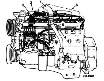
Remove turbocharger to intercooler pipe (1, Fig.
4 or 4a).
2.
Disconnect water inlet (2) and outlet hoses (3) at
intercooler.
3.
Remove fuel lines (as an assembly) as follows:
a.
disconnect fuel lines at injection nozzles
and pump.
b.
(Figure 4 only) loosen clamps (4 and 5)
which secure fuel lines to the intercooler.
c.
(Figure 4a only) disconnect fuel return line
(4).
d.
remove fuel lines and cap all openings.
Figure 4. - Left Side View (DTI-466B)
(with UTDS* Model 100 Fuel
Injection Pump)
1. Turbo Outlet Pipe
4. Clamp
2. Water Inlet Pipe
5. Clamp
3. Water Outlet Tube 6. Aneroid Tube
4.
Remove aneroid tube (6, Fig. 4 or 5, Fig. 4a) and
cap openings.
5.
Remove bolts securing intercooler to cylinder
head; then remove intercooler gasket.
Figure 4a. - Left Side View (DTI-466C)
(with Robert Bosch Model MW
Fuel Injection Pump)
[With Intercooler]
1.
Turbo Outlet Pipe
4.
Fuel Return Line
2.
Water Inlet Pipe
5.
Aneroid Tube
3.
Water Outlet Tube 6.
Intercooler (outline)
*United Technologies Diesel Systems
(formerly AMBAC)
CGES-185-3
PRINTED IN UNITED STATES OF AMERICA
Page 4


