SERVICE MANUAL
MANIFOLDS
Section 2
REMOVAL AND DISASSEMBLY
Remove Manifolds as Follows:
INTAKE MANIFOLD - (D and DT Engines)
1.
Disconnect Turbocharger crossover tube (2, Fig.
3 or Fig. 3a) (if equipped) from intake manifold
(1).
2.
Remove fuel lines (as an assembly) as follows:
a.
Disconnect fuel lines (3, Fig. 3 or 3, Fig. 3a)
at injection nozzles and pump.
b.
(Engines equipped with UTDS* Model 100
Fuel Injection Pump only) Loosen clamp (4)
securing fuel lines to the hose connecting
final fuel filter to injection pump.
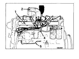
Figure 3. - Left Side View DT-466 (w/UTDS*
Model 100 Fuel Injection Pump)
1.
Intake Manifold
2.
Outlet Pipe
3.
Fuel Lines
4.
Clamp
5.
Lube Oil Tube
*United Technologies Diesel Systems
(formerly AMBAC)
c.
After removing fuel lines cap all Injection
nozzle openings, pump and line openings
to prevent dirt from entering.
3.
Remove cap screws securing Intake manifold to
cylinder
head;
then
remove
manifold
and
manifold gasket.
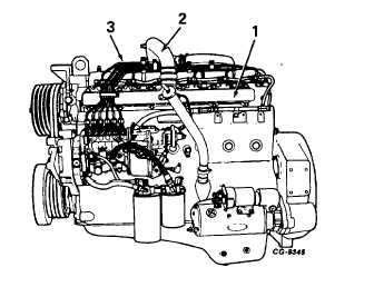
Figure 3a. - Left Side View DT466C
(w/Robert Bosch Model MW Fuel
Injection Pump)
1.
Intake Manifold
2.
Outlet Pipe
3.
Fuel Lines
CGES-185-3
PRINTED IN UNITED STATES OF AMERICA
Page 3