SERVICE MANUAL
CONNECTING RODS, PISTONS, RINGS & SLEEVES
Section 5
NOTE: If all counterbore ledges of one particular
engine are to be counterbored to the same depth,
take measurement of aft counterbores and set up
counterboring tool on lowest counterbore ledge, to
insure clean-up of all counterbores.
c.
Hold onto handle (1) and pull out on plunger
(9).
d.
Slowly and gently lower tool holder into
counterbore, to avoid damage to the tool
bit.
e.
Engage larger diameter of tool holder into
counterbore and allow tool bit to rest on
counterbore ledge.
f.
Loosen locking screw (10) and rotate
adjusting
nut
(2)
in
a
CLOCK-WISE
DIRECTION
until
tool
bit
clears
the
counterbore ledge.
g.
Tighten locking screw.
h.
Assemble
hold-down
cap
screws
and
washers (5) through adapter plate (6) into
cylinder block finger-tight.
i.
Tool holder must rotate freely.
j.
Torque cap screws to 45 N•m (33 Ibf-ft).
Tighten each cap screw only a small
amount before final torquing. Then cross-
tighten in diagonal sequence.
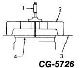
6.Measure depth of counterbore as follows:
a.
Using a depth micrometer (1, Fig. 26)
measure from the top surface of adapter (2)
to deck of crankcase (3) and record
measurement.
b.
Then, measure from top surface of adapter
plate to counterbore ledge (4) and record
measurement.
c.
Subtract No. 1 reading from No. 2 reading,
and this is the depth of the counterbore
ledge as exemplified below.
EXAMPLE:
No. 1 Reading -
Top of Adapter Plate
to Counterbore Ledge
2.125"
No. 2 Reading -
Top of Adapter Plate
to Deck of Cylinder Block
-1.750"
Depth of Counterbore =
.375"
Figure 26. - Depth Measurement of Counterbore
1. Depth micrometer
2. Adapter plate
3. Deck of engine block
4. Counterbore ledge
7.Operate counterboring tool as follows:
a.
Loosen locking screw (1, Fig. 27).
b.
Rotate adjusting nut (2) in counter-
clockwise direction until tool bit is resting on
the lowest part of the counterbore ledge
and there is clearance between the housing
(5) and the adjusting nut.
c.
The distance between the housing and
adjusting nut equals the amount of material
that will be removed from the counterbore
ledge.
d.
The adjusting nut has graduated markings
to estimate the amount of the cut. Each
mark is 0.03 mm (0.001 in.)
NOTE: Never attempt to remove more than 0.13 mm
(0.005 in.) of material at one setting.
CGES-185-3
PRINTED IN UNITED STATES OF AMERICA
Page 24