SERVICE MANUAL
CONNECTING RODS, PISTONS, RINGS & SLEEVES
Section 5
INSTALLATION
Install Cylinder Sleeves as follows:
1.
Clean and dry the bore (in the crankcase) and flange
counterbore. Also clean and dry the sleeve.
NOTE: When a new piston or a new piston and
connecting rod assembly are being Installed, install
a matched set of pistons and sleeves.
2.
Check Cylinder Sleeve Protrusion as follows:
a.
Place each sleeve in the crankcase without
the “O” Rings. Clamp the sleeve down
using three holding adapters as shown in
Fig. 30. (Make sleeve holding adapters
locally).
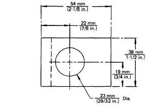
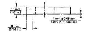
Material: Cold Rolled Steel
CG-5757
Figure 30. - Cylinder Sleeve Holding Adapter
Specifications
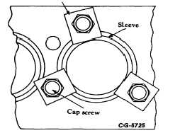
b.Use one of the hardened washers under
each cap screw. Space the bolts to obtain
uniform pressure on the sleeve flange as
shown in Fig. 32. Torque the bolts in three
stages: 55 N•m (40 Ibf-ft), 1 10 N•m (80
Ibf-ft) and 165 N•m (1 20 Ib. ft).
Holding Adapter
Figure 31. - Holding Adapter with Hardened Washers
c.
Place a dial indicator, with block, across the
cylinder sleeve.
d.
With the dial indicator set on the flange of
the cylinder sleeve, adjust the indicator to
zero. Move the indicator block until the
pointer drops to the crankcase deck and
take a reading.
e.
If the sleeve flange is below the crankcase
deck, rest the indicator pointer on the
crankcase deck and set the indicator at
zero. Move the indicator block until the
pointer drops to the sleeve flange and take
a reading.
CGES-185-3
PRINTED IN UNITED STATE OF AMERICA
Page 27