SERVICE MANUAL
CRANKSHAFT, MAIN BEARINGS, FLYWHEEL & CRANKCASE
Section 6
5.
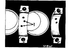
Inspect the 12 piston oil jet tubes used in
Turbocharged Engines. Be sure they are open
and clean as shown in Fig. 19.
Figure 19. - Piston Oil Jet Tubes
1.
Oil jets
NOTE: DO NOT remove oil jets unless damaged.
6.
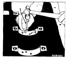
If tubes are damaged replace as follows:
a.
Remove damaged tubes with a pilot driver
(1, Fig. 20) as shown.
b.
Install new oil jet tubes with the same pilot
driver shown in Fig. 20.
c.
The jet tube (when installed) must not
project above the surface; but must be
recessed 3 mm (1/8 inch) below the
surface as shown in (2, Fig. 20).
Figure 20. - Removing/Installing Piston Oil Jet Tubes
1.
Pilot driver
2.
Oil jet tube
d.
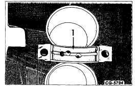
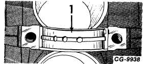
The top half of the main bearing insert (1,
Fig. 21) is slotted to provide a flow of oil to
the Jet tubes and camshaft bushings as
shown.
Figure 21. - Main Bearing Insert - Old Style Shown
w/OFFSET Piston Oil Jet Tube Holes
Figure 21A. - Main Bearing Insert - New Style w/Piston
Oil Jet Tube Holes in Line
7.
Repairs for coolant or oil leaks in crankcase
casting can be performed in areas shown in
Figure 21B only. Instructions are as follows:
Restrictions:
a.
No repairs may be made within one inch of
an internal rib, wall or boss casting.
b.
Casting cracks can not be repaired.
c.
Leak to be repaired must be within tap drill
diameter.
d.
Maximum plug size allowed for repair is
1/4-18 NPTF.
e.
Leaks to be plugged (repaired) must be at
least 3 inches apart.
CGES-185-3
PRINTED IN UNITED STATES OF AMERICA
Page 16