SERVICE MANUAL
CRANKSHAFT, MAIN BEARINGS, FLYWHEEL & CRANKCASE
Section 6
7.
Subtract dimension "A" of the OLD cap from
dimension "A" of the NEW cap and record the
difference. Mill or grind this amount from
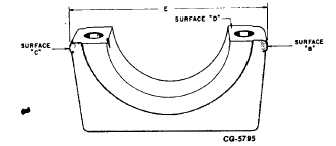
surface "C" (Fig. 27) of the new cap. Dimension
"A" of both caps will now be equal.
Figure 27. - Bearing Cap Finished Length
Surface "C"
Surface "B"
Surface "D"
NOTE: Surface "C" (Fig. 27) must be held square
with surface "D" and parallel to the bearing bore.
8.
Mill or grind surface "B" (Fig. 27) of the new cap
until the dimension "E" 153.67153.72 mm
(6.050-6.052 in.) shown from surface "C" to "B"
is obtained.
NOTE: Surface "B" (Fig. 27) must be held square
with surface "D" and parallel to the bearing bore.
Fit Main Bearings in Main Bearing Caps as follows:
1.
Install a new bearing in a new bearing cap or the
original bearing in the original bearing cap, as
called for.
2.
Check the bearing clearance as follows:
NOTE: DO NOT turn the crankshaft during this
procedure.
a.
Clean the bearing surface and the
exposed half of the crankshaft journal.
Be sure these surfaces are free of oil.
b.
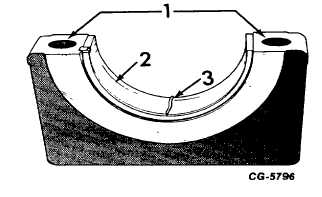
Place a suitable length of 0.010 inch
virgin lead wire or a piece of
Plastigage across the bearing surface
as shown in Fig. 28.
Figure 28. - Position of Virgin Lead or Plastigage
1.
Surface "D"
2.
Bearing
3.
Plastigage
c.
Install the bearing cap and torque the cap
screws to 155 N•m (115 Ibf-ft).
d.
Remove the bearing cap. When virgin
lead is used, measure the crushed
thickness with a micrometer and record the
results. When Plastigage is used, the
flattened plastic material will be found
adhearing to either the bearing or the
crankshaft.
DO
NOT
remove
the
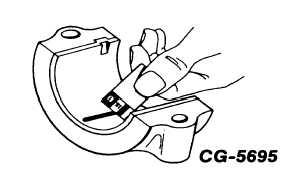
plastigage. Determine bearing clearance
by comparing the width of the flattened
plastic with the graduations on the envelope
as shown in Fig. 29.
Figure 29. - Reading Bearing Clearance with Plastigage
CGES-185-3
PRINTED IN UNITED STATES OF AMERICA
Page 22