SERVICE MANUAL
DISASSEMBLY
Section 2
34.
Remove four capscrews and lockwashers from
camshaft bearing retainer on drive end of pump
(Figure 30).
Figure 30.
1. Retainer Mounting Screws
2. Oil Drain Hole
35.
Remove rack screws, lockwashers and retaining
plate (Figure 31). Pull rack out of pump housing.
Figure 31.
1.
Control Rack
3.
Screws
2.
Guide Pin
Injection pump housing is now ready for inspection.
ANEROID
The aneroid (Figure 32) should be disassembled,
cleaned and inspected when the injection pump is
disassembled
or
if
the
aneroid
is
suspected
of
malfunction. The diaphragm assembly must be replaced
if signs of leakage, cracking or hardening exist. Replace
o-ring on diaphragm stop.
IMPORTANT
TO
REPLACE
A
LEAKING
ANEROID
DIAPHRAGM, THE INJECTION PUMP MUST
BE
REMOVED,
THE
NEW
DIAPHRAGM
INSTALLED AND THE INJECTION PUMP
RECALIBRATED. DO NOT ATTEMPT TO
REPLACE
THE
ANEROID
WITHOUT
RECALIBRA-TING THE INJECTION PUMP.
SEEMI-NGLY SMALL CHANGES TO THE
INJECTION
PUMP
CONTROL
RACK
SETTINGS CAN DESTROY THE ENGINE.
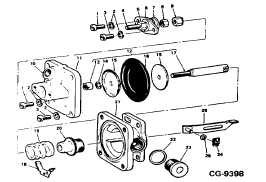
Figure 32. Exploded View of Aneroid
1.
Screw
15. Seat
2.
Washer
16. Diaphragm
3.
Screw (w/Seal Hole) 17. Shaft
4.
Pin
18. Clip
5.
Nut
19. Spring
6.
Stop Assy.
20. Bushing
7.
O-Ring
21. Housing
8.
Nut
22. Gasket
9.
Nut
23. Plug
10.
Bushing
24. Clip
11.
Cover Assy.
25. Washer
12.
Shaft Assy.
26. Max. Fuel Aner-
13.
Nut
oid Shackle
14.
Washer
CGES-375
Printed in United States of America
Page 13