SERVICE MANUAL
DISASSEMBLY
Section 2
Figure 27. Tappet Removal (If Tappet Depressor Tool
KDEP 1505 is not available)
1.
Tappet Holder
4. Left Lever
2.
Clamping Device
5. KDEP 1067
3.
Right Lever
6. Spacer Plate
Location
b.
Position right lever (3, Figure 27) and then
left lever (4) over first two tappets. Adjust
crossbar (5) up or down to make levers
point up slightly when resting on tappets.
c.
Holding one hand on tappet holder (1,
Figure 27), depress left lever compressing
both springs to unload and remove tappet
holder. Hold onto holder when depressing
tappets because foot of holder is spring
loaded and tool will spring out.
28.
Repeat procedure for the next four tappets.
29.
Remove each roller tappet, lower spring seat,
plunger and spring.
IMPORTANT
KEEP PARTS FOR EACH CYLINDER
TOGETHER.
30.
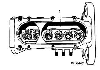
Position rack so control sleeve ball is in notch of
pump housing (Figure 28).
Figure 28. Rack Positioning
1.
Control Sleeve Ball
31.
Remove control sleeves and upper spring seats.
32.
Remove tappet depressor tool (or, if used,
remove pump from spring compressor KDEP
1067).
BARREL REMOVAL
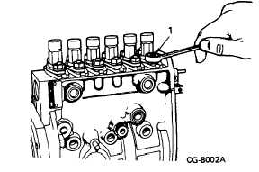
33.
Remove barrel flange nuts and lockwashers
(Figure 29) (assembly jig KDEP 1066 may be
used). Remove each barrel from housing. Store
each barrel with its plunger and shims.
Figure 29. Barrel Removal
1.
Flange Nuts
CGES-375
Printed in United States of America
Page 12


