SERVICE MANUAL
4.
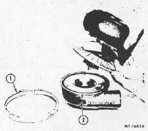
Remove the clamp or capscrews and lock plates
and stand the turbocharger on the bench as
shown in Fig. 12. Carefully lift the turbine
housing with center housing attached from the
compressor housing. A light tapping with a
rubber mallet on the compressor mounting
flange may be necessary as lifting pressure is
applied.
Fig. 12. Removing Compressor Housing
1. Clamp
2. Compressor Housing
5.
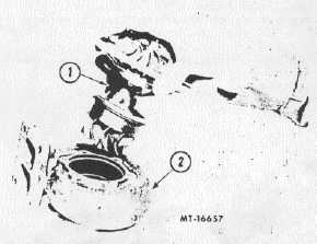
Straighten tabs on the lock plates and remove
capscrews, lock plates and clamps securing the
center housing to the turbine housing. Carefully
lift the center housing assembly from the turbine
housing (Fig. 13). A light tapping with a rubber
mallet on turbine housing mounting flange may
be necessary as lifting pressure is applied.
Do not test center housing on either
compressor or turbine wheel or damage to wheel
will result.
Fig. 13. Removing Center Housing From Turbine
Housing
1. Center Housing
2. Turbine Housing
Where it is not desired to completely
disassemble the turbocharger, a replacement
core assembly has been made available. When
using this unit, it is only necessary to remove the
turbine and compressor housings from the old
unit and install them on the new core assembly.
6.
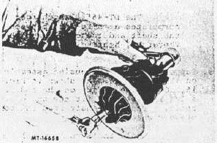
Remove the locknut from the turbine shaft (Fig.
14):
Do not apply side thrust when loosening the
lock nut as it is possible to bend the shaft.
Fig. 14. Lock Nut Removal
CTS-4104
PRINTED IN UNITED STATES OF AMERICA
Page 11


