TM 5-3825-225-14&P
(c)
Internally stepped compression.
(d)
Laminated segment oil control.
(e)
Slotted scraper.
(9)
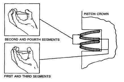
Install laminated rings. The procedure for fitting the laminated type is different because the ring has four
separate segments. These may be fitted by hand in the following sequence with the piston crown
uppermost:
(a)
Install the first segment to the piston (5) so that when held horizontally between the thumb and
fingers and radially compressed, the ring ends point downward (see Figure 5-22). Place this ring
on the bottom face of the fourth ring groove with the gap over the piston pin bore.
(b)
Install the second segment on top of the first, so that when compressed as described above the
ends point upward. Position the gap at 180 to that of the first segment.
(c)
Install the third segment as in (a) above with the gap immediately above the gap of the first
segment.
(d)
Install the fourth segment as in (b) above with the gap immediately above the gap of the second
segment. If all the segments have been fitted correctly, they will be positioned as shown Figure 5-
22. The gaps of the remaining rings should be staggered alternately along the piston pin axis.
(10) Liberally lubricate the rings (1) in their grooves and ensure that they move freely. This does not apply to
the laminated type in the fourth groove, which if correctly fitted should not move freely due to the
outward pressure of the top and bottom segments on the ring groove walls. When all the rings have
been fitted, they should be as shown in Figure 5-22.
(11) Install spring loaded scraper ring. When fitting the chrome plated spring loaded scraper ring (see Figure
5-23), the following should be adopted:
(a)
Install internal expander (1, Figure 5-23).
NOTE
When fitting rail rings, gaps should be staggered.
(b)
Install two rail rings (2) at the bottom of the groove.
(c)
Install spiral ring (3).
(d)
Install two top rail rings (2).
Figure 5-22. Piston Ring Installation.
TA506341
5-21


