TM 5-3825-225-14&P
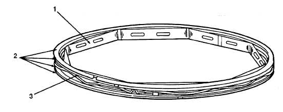
Figure 5-23. Scraper Ring.
e. Installation(see Appendix E Figure 54).
(1)
Before fitting the piston (5) and connecting rod assemblies (6) to their respective cylinder bores,
thoroughly clean and liberally coat each bore with clean engine oil.
(2)
Turn the engine until the crankpins of no. 1 and no. 4 cylinders are at BDC.
(3)
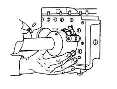
Using a suitable ring clamp as shown in Figure 5-24, carefully compress the rings of no. 1 piston and
hold in this position.
(4)
With the word FRONT on the connecting rod facing the front of the engine, insert the rod carefully into
no. 1 cylinder bore.
(5)
The piston head may be gently tapped with the shaft of a hammer until all the rings have entered the
cylinder bore.
(6)
Draw the connecting rod (6) toward the crankpin, and place the top half bearing shell in position. Locate
the tag in the machined slot and oil it liberally. Draw the rod onto the crankpin.
(7)
Install the lower half bearing shell (11) to the connecting rod cap. Locating the tag in the machined slot,
liberally oil and fit the cap to the crankpin, ensuring that the numbers on the rod and cap coincide (see
Figure 5-20).
Figure 5-24. Piston Installation .
NOTE
The cylinders are numbered 1, 2, 3, and 4
starting from the front (water pump) end of
the engine. These components (marked as
shown in Figures 5-20 and 5-21) must be
returned to their original locations.
NOTE
Locking tabs are not fitted to these setscrews.
(8)
Install the two connecting rod securing setscrews (10) and torque venly to 42 lb-ft. (57 Nm).
(9)
Repeat this procedure for no. 4 piston and connecting rod assembly.
(10) Rotate the crankshaft to bring crankpins of no. 2 and no. 3 cylinders to BDC.
(11) Repeat steps (3)-(8) to install the two remaining piston and connecting rod assemblies.
TA506342
5-22