CONTROL & RELEASE EQUIPMENT
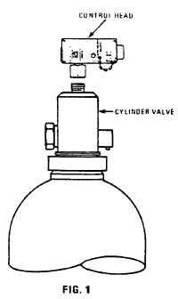
There are two principle parts in the control and release
portion of the system: (a) the cylinder valve, and (b) the
control head. See Figure 1.
Halon 1301 is stored in the steel cylinder as a liquid
which is super-pressurized by nitrogen to 360 psig at
700 F.
VALVE
The discharge valve operates on a principle whereby the
cylinder pressure is used to effect the release of the
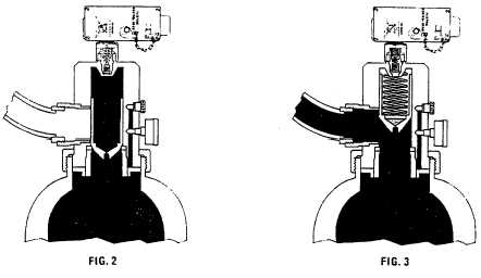
agent. In a normal standby situation, the pressure on
both sides of the valve piston is equalized by a small
interconnecting orifice through the piston. This provides
a differential force to hold the valve closed (See Figure
2). When the extinguishing system is actuated, the
control head which is mounted on top of the cylinder
valve depresses a pilot check. This allows the pressure
above the piston to vent rapidly to atmosphere, reversing
the differential pressure force. The piston is then driven
to the open position allowing the agent to be discharged.
See Figure 3.
The discharge valve incorporates a safety release burst
disc which is designed to release at 750-900 psig
through an anti-recoil plug to atmosphere.
Where the size or type of hazard requires more than one
cylinder of Halon 1301, the cylinders are manifolded
together. In these multiple cylinder installations of more
than two cylinders, a pair of cylinders is fitted with control
heads. These are known as control or master cylinders.
The other cylinders are called slave cylinders.
When the system operates, the Halon 1301 from these
control cylinders pressurizes the manifold connecting all
the cylinders thus releasing the content in the balance of
the cylinders. The pressure-operated or slave cylinders
are identical to control cylinders except they are not
fitted with control heads.
5


