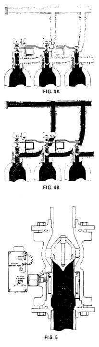
Figure 4A shows the position of parts on pressure-
operated cylinders ready to operate.
Figure 4B shows the parts during operation.
The pressure causes the piston to depress therefore
venting the upper cavity in the valve. Once vented, the
main seat opens automatically.
Figure 4A shows a typical multiple cylinder assembly
showing the manner in which the two control cylinders
are manifolded to the other cylinders in the system.
Note that Halon 1301 flows from the discharge flexible
loop to the pressure-operated control head.
Structural steel framing or racks are supplied with each
system for supporting the cylinders and manifold.
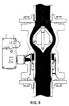
DIRECTIONAL VALVE SYSTEM
In some instances it may be necessary to protect more
than one hazard with the same bank of cylinders. In
these cases, pressure-operated stop valves are used to
route the Halon 1301 to whichever space in which a fire
occurs. These valves are available to complement the
cylinders' releasing equipment in order to permit
flexibility of installation.
When a fire occurs in one of the compartments with a
directional valve system, the detecting equipment via a
control panel performs the following functions:
1.
Opens the proper directional valve
2.
Releases the Halon 1301 cylinders
6