ELECTRIC OPERATION
The opening of the directional valve is accomplished by
fitting the directional valve with an electric control head.
Figure 5 shows the assembly of a pressure-operated
directional valve and an electric control head in its
closed position.
When the Halon 1301 being discharged reaches the
closed valve, it enters an auxiliary annular cavity around
the main valve seat. Figure 5 shows the location of the
pressurized gas which is dead-ended against the pilot
seat. Once the pilot seat is depressed by the electric
control head, the pressurized gas generates a force on
the piston which has been compressing the spring and
holding the valve closed. The valve, as a result of this
pressure, opens instantly.
The valve design is unique in the fact that it is an in-line
type having very little pressure drop across the seat.
Figure 6 shows the position of the parts of the valve
while the valve is open during operation.
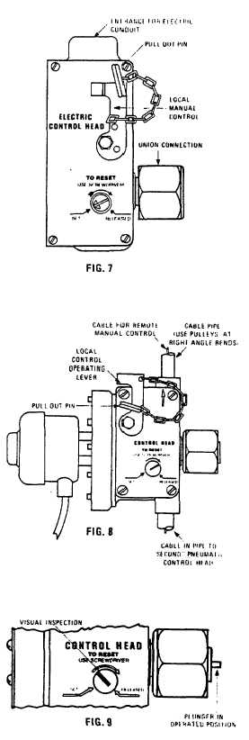
ELECTRIC CONTROL HEAD
The electric control head (see Figure 7) is available for
use with various voltages. When heat due to fire causes
the detector to close and complete the electric circuit,
electric energy operates a solenoid in the electric control
head which trips a lever mechanism releasing a spring to
drive the plunger forward to open the pilot seat. The
electric control head can be operated from a remote
point utilizing manually operated switch cases.
This control head includes an important maintenance
feature: it can be removed from the cylinders for check-
out. Visual checks can be made to verify actuation by
manually operating the system.
EXPLOSION PROOF ELECTRIC CONTROL HEAD
The explosion proof electric control head is available
with various voltages. It is suitable for use in Class 1,
Groups C & D type environments as specified in the
National Electrical Code.
The explosion proof head like the electric head is
operated by the movement of the solenoid that trips a
lever mechanism releasing a spring that drives a plunger
forward to open the pilot seat. See Figure 8.
CONTROL HEAD INSPECTION
After operation, it is not necessary to replace any control
head parts. The control head is reset by using a
screwdriver to turn the reset shaft from "released"
position to "set" position. See Figure 9. The head is
also fitted with an emergency manual control. The
manual control can be utilized by pulling out the safety
locking pin, and then operating the lever.
An important advantage in the design of the control head
is that visual inspection is all that is needed to determine
whether the head has operated. If the reset shaft has
rotated to "released" position then the head has
operated.
In fact, no replacement parts are required to recondition
a discharged system at recharge.
7