SERVICE MANUAL
CYLINDER HEAD & VALVES
Section 3
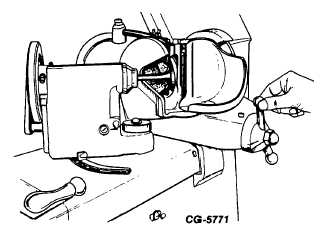
Figure 28. - Grinding Valve Face Angle
d.
Replace valve if more than 0.20 mm (0.008
in) stock is removed from valve face angle
or
if
margin
falls
below
minimum
specifications.
e.
Check valve face runout, after resurfacing,
with dial indicator.
f.
Replace valve if runout (in reference to
valve stem) is greater than 0.05 mm (0.002
in) total variation in dial indicator reading.
g. After resurfacing valves, clean valve guides
and check valve face contact with valve seat
using Prussion blue as follows:
1.
Spread thin film of Prussion blue on
valve face. Insert valve into its guide.
2.
Apply pressure on exact center of
valve head, while making a quarter
turn in the seat.
3.
Remove valve, inspect impression
made on seat and on valve face.
4.
Bluing should appear around entire contact
surface of valve face and valve seat to be
acceptable. CHECK SEVERAL TIMES TO
PREVENT ERROR. If acceptable, proceed with
valve installation.
5.
If bluing DOES NOT show around the ENTIRE
contact surface of the valve seat, the angles do
not match and are UNACCEPTABLE. If this
happens, correct by RESURFACING VALVE
SEATS; NOT VALVE FACES.
5.
Resurface valve seat as follows:
a.
Dress the grinding wheel to correct angle.
Lightly lubricate and install correct size pilot
into valve guide bore.
b.
Lower grinder head over pilot shank until
wheel barely clears the valve seat. Turn on
power. GENTLY apply grinding wheel to
valve seat with little pressure other than
weight of the wheel.
c.
Raise
wheel
frequently
to
prevent
overheating.
d.
Grind seat to a smooth even surface.
e.
Check seat concentricity, roundness and
valve face contact using Prussion blue as
previously outlined.
f.
After grinding seats, it may be found that
seats are wider than the specified width, as
shown in Fig. 29.
CGES-185-3
PRINTED IN UNITED STATES OF AMERICA
Page 22