SERVICE MANUAL
CYLINDER HEAD & VALVES
Section 3
e.
Use valve guide installer (See Introduction
for tool list) to install new guide. Keep valve
guide recession from cylinder head surface
at limits specified below:
NOTE: Install valve guides with (internal) threaded
portion down. The 30 degree chamfer at the top of
the guide is Intended to allow excess oil to drain
away from the top of the guide and the threads are
intended only to distribute the small amount of oil
which enters the guide, not to introduce oil.
Inverting the guides can lead to excessive oil
consumption.
300 SERIES
Intake
Exhaust
25.20 mm (0.992 in)
32.31 mm (1.272 in)
25.70 mm (1.012 in)
32.82 mm (1.292 in)
400 SERIES
Intake
Exhaust
30.66 mm (1.207 in)
32.69 mm (1.287 in)
31.17 mm (1.227 in)
33.20 mm (1.307 in)
Inspect and Repair Valves as follows:
1.
Visually INSPECT each valve for excessive
WEAR, BURN MARKS, WAR- PAGE, PITTING
or SCUFFING at:
a.
Valve Stem Grooves.
b.
Valve Stems.
c.
Valve Heads
2.
Replace valves which are seriously bent, worn,
burnt, warped, pitted or scuffed.
3.
Resurface valve face angle, if necessary.
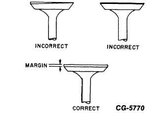
a.
Maintain a minimum valve face margin of
1.73 mm (0.068 in) for intake valves and
1.14 mm (0.045 in) for exhaust valves on
300 Series engines.
b.
On 400 Series engines maintain a minimum
valve face margin of 2.24 mm (0.088 in) for
intake valve and 1.14 mm (0.045 in) for
exhaust valves. See Fig. 26.
Figure 26. - Examples of Valve Face Margin
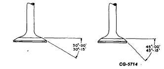
c.
Maintain valve face angles as shown in Fig.
27.
Figure 27. - Valve Face Angles (300/400
Series)
NOTE: An incorrect margin will not provide proper
heat dissipation and lead to warpage or breakage.
4.
Resurface valve face angle as follows:
a.
Set valve in grinder to desired angle.
b.
Dress the wheel to proper angle.
c.
Take a light cut-off valve face angle
surface, as shown in Fig. 28.
CGES-185-3
PRINTED IN UNITED STATES OF AMERICA
Page 21