SERVICE MANUAL
CYLINDER HEAD & VALVES
Section 3
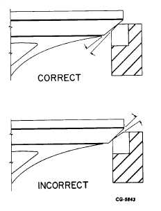
Figure 29. - Valve Seat Width
g.
Correct wide valve seats by grinding top edge of
seat with a stone mounted on grinder head. The
stone must be a smaller angle (preferably 1 5
degrees) than the valve seat.
NOTE: If valve does not seat properly after
resurfacing valve seats, replace valve seats.
6.
Replace valve seat as follows:
a.
Remove valve seats with a slide hammer
and expanding screw with pre-cup puller.
Two pre-cup pullers are available for
service one for intake, one for exhaust
valves. (See Tool List for tool numbers).
b.
Clean counterbore (in head), to assure
proper valve seat mating and good heat
transfer.
c.
If right fit is NOT assured between mating
surfaces of valve seat and cylinder head
counterbore, install oversize valve seat
inserts as follows:
1.
Take a light cut from bottom of insert
counterbore
in
cylinder
head
to
dimensions shown in the valve seat
insert chart for correct fit.
2.
Maintain radii shown in Fig. 30 when
enlarging counterbore for oversize
inserts.
VALVE SEAT INSERT CHART (OVERSIZE)
DIAMETER OF CYLINDER HEAD COUNTERBORE*
Oversize
Engine
Insert
Intake
Exhaust
Naturally Aspirated
002 in
None
38.96-38.99 mm (1.534-1.535 in)
312 and 360
**.005 in
None
3904-39.07 mm (1 537-1.538 in)
015 in
None
39.29-39 32 mm (1.547-1.548 in)
.002 in
45.19-45.21 mm (1.779-1.780 in) 38.96-38.99 mm (1.534-1.535 in)
Turbocharged 360
**.005 In
45.26-45.29 mm (1.782-1.783 in) 39.04-39.07 mm (1 537-1.538 in)
.015 in
45.52-45.54 mm (1.792-1.793 in) 39.29-39.32 mm (1.547-1 548 in)
All 414,
.002 in
50.75-50.77 mm (1.998-1.999 in) 41.30-41.33 mm (1.626-1.627 in)
436 and 466
**.005 in
50.83-50.85 mm (2.001-2.002 in) 41.38-41 40 mm (1.629-1.630 in)
.015 in
51.08-51 10 mm (2.011-2.012 in) 41.63-41.66 mm (1.639-1.640 in)
*It is not necessary to enlarge the Insert counterbore before Installing the standard size Insert.
** .005 Inch oversize Insert is no longer available for service.
CGES-185-3
PRINTED IN UNITED STATES OF AMERICA
Page 23


