SERVICE MANUAL
REASSEMBLY
Section 4
PUMP ASSEMBLY
1.
It is suggested that all delivery valves and
plunger and barrel assemblies be inspected and
ready prior to pump reassembly.
While still in assembly jig KDEP 1066 install
copper gasket, delivery valve, spring and washer
into barrel. Tighten delivery valve holder nut with
O-ring to specifications (see torque chart Section
1, Page 10).
IMPORTANT
DELIVERY VALVE HOLDER MUST BE
TIGHTENED (SEE TORQUE CHART,
SECTION 1, PAGE 10) OUTSIDE OF
PUMP
PRIOR
TO
PUMP
REASSEMBLY.
All parts must be returned to their original
position. Clean fuel oil or calibration oil must be
available for lubricating the individual parts prior
to assembly.
BARREL
2.
Install barrel lower O-ring in housing. Install
barrel lower spacer ring in pump housing, if it
was removed, using 9 681 238 902.
3.
Assemble impact cap with snap ring and O-ring
onto barrel. Be sure hole in impact cap does not
line up with spill/fill port in barrel.
4.
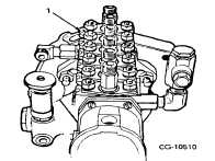
Lubricate O-ring and lower surface of barrel,
and install barrel with adjustment slot on the
barrel flange opposite the control rack (Figure 1).
Figure 1. Adjustment Slot Location
1.
Adjustment Slot
Push down with hand pressure: the barrel
should stay down when pressure is released. If
not, remove barrel and check for pinched O-
ring.
5.
Install spacer plates KDEP 1057 under barrel
flanges and install flat washer, lockwasher and
nuts. Tighten to specifications. Install fitting
locks, flat washer, lockwasher and nuts.
6.
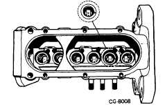
Turn pump upside down. Install each plunger in
correct barrel. Position the notch on the plunger
foot so it points away from the rack, thus sealing
the port (Figure 2)
Figure 2.
1.
Plunger
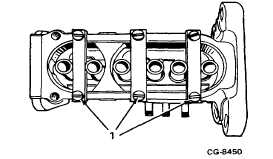
7.
Install plunger retainersKDEP1052 (Figure3).
Figure 3. Install Plunger Retainers
1. Plunger Retainers
CGES-375
Printed in United States of America
Page 1