SERVICE MANUAL
REASSEMBLY
Section 4
8.
Connect air coupling to intake of gallery and plug
return port. Submerge pump housing in an oil
bath and pressurize pump to 5 bar (75 PSI).
Look for leakage (bubbles) from top and bottom
of pump. Any bubbles other than small bubbles
coming from inside plunger retainer tubes
indicates a leak. Correct any leaks found. If no
leaks are found remove air hose, gallery outlet
plug, plunger retainers and plungers.
9.
Loosen barrel retaining nuts and back off so
washers are loose.
PLUNGER AND RACK
10.
Install control rack and fasten retaining plate with
two screws and lockwashers. Check rack for
freedom of movement.
11.
Insert each control sleeve after positioning rack
so that the control sleeve ball will fall into the slot
of the control rack (Figure 4).
Figure 4. Control Sleeve Ball Positioning
1.
Control Sleeve Ball
12.
When all control sleeves are installed, move
rack back and forth to make sure control sleeves
all move freely and together.
13.
Coat each upper spring seat with grease and
stick upper spring seat to spring.
14.
Insert each spring and upper seat into pump
housing.
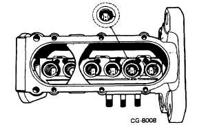
15.
Insert each plunger into correct barrel. Make
sure each plunger foot is positioned so that
notch on plunger foot points away from control
rack (Figure 5).
Figure 5.
1.
Notch on Plunger Foot
17.
Move rack back and forth and watch plungers.
The control rack should move freely without
binding and the plungers should rotate together.
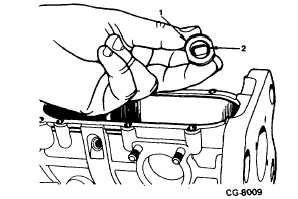
18.
Coat each lower spring seat with grease. Stick
lower spring seat on each roller tappet (Figure
Figure 6. Tappet and Spring Seat
1.
Tappet
2.
Spring Seat
CGES-375
Printed in United States of America
Page 2