SERVICE MANUAL
REASSEMBLY
Section 4
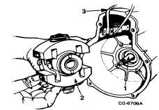
Figure 10. Installing Flyweight Assembly
1. Camshaft
3. Rubber Band or Wire
2. Flyweight Assembly
6.
Install slider and floating lever open slot of
floating lever to right. Pin floating lever to rack
link to hold in place.
7.
Check "slider-to-housing" distance with guide
bolt gauge 1 682 329 038 (Figure 11). Notch in
gauge must fit in groove on guide bushing when
gauge is placed against mating surface of
housing (no gasket)
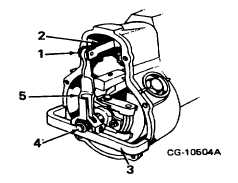
Figure 11. Slider-to-Housing Distance
1.
Pin
4.
Adjusting Pin
2.
Rack Link
5.
Floating Lever
3.
Guide Bolt Gauge
1 682 329 038
NOTE: If guide bolt gauge 1 682 329 038 is not
available use a depth micrometer to measure from back
of slider to governor mating surface (no gasket) (Figure
12). Distance (item 4) should be 39.15 i .2 mm (1.54 ±
.008").
Adjust by turning screw inside of guide bushing.
Back screw out to increase distance or turn
screw in to decrease distance (one half turn of
screw moves sliding block approximately .5 mm
(.020").
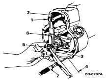
Figure 12. Measuring Slider-to-Housing Distance (If
Guide Bolt Gauge 1 682 329 038 is not available)
1.
Pin
5.
Guide Bushing
2.
Rack Link
6.
Floating Lever
3.
Slider
7.
Depth Micrometer
4.
Slider-to-Housing
Distance
8.
Secure double-nutted thru-bolt in governor
weight assembly by installing lockwasher and
nut. Bend over tabs of lockwasher to secure.
Operate rack back and forth to recheck all
linkage for free movement.
Remove seal cover from hi-idle adjusting screw
locknut on governor cover and back out hi-idle
adjusting screw. Hi-idle screw is removed so
that control lever can be moved full forward for
making next check.
Check "basic setting of S-plate", the distance
from governor cover surface (gasket in place) to
guide pin shaft when guide pin is in maxim fuel
position and bottomed in S-plate. Using S-plate
gauge 9 681 238 904 (Figure 13), notch in tang
of gauge should fit over guide pin shaft when bar
is placed on governor cover surface (gasket in
place).
CGES-375
Printed in United States of America
Page 5