SERVICE MANUAL
REASSEMBLY
Section 4
13.
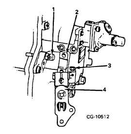
Position control lever fully back against loidle
stop screw.
Figure 16. Accelerator Lever Assembly
1. Full Load Position
3. Low Idle Position
2. Governor Control Lever
4. Accelerator Lever
14.
Insert aneroid assembly into governor housing.
Rotate aneroid assembly approximately 45
degrees in the counterclockwise direction (from
installed position). Slide aneroid assembly into
governor housing, then rotate aneroid assembly
45 degrees clockwise to the horizontal position
(Figure 17).
15.
Move control lever to the vertical position.
NOTE: To ease this operation, interior of governor
housing can be lighted by removing seal wire and plug
from governor adjustment access cover on side of
governor housing and inserting penlight through access
hole.
16.
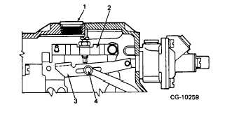
After aneroid strap is engaged with rocker arm
pin, push aneroid assembly into position against
governor housing and secure with 4 mounting
screws.
Figure 17. Engaging Aneroid Strap to Rocker Arm Pin
(Governor Housing Cut Away for Illustration.)
1.
Starting Fuel Cut-Out
2.Rack Link
Speed Adjustment
3.Max. Fuel
Shackle
Access Hole
4.Rocker Arm Pin
Check aneroid assembly as follows:
a.
Hold accelerator lever full forward. This
should place rack in excess fuel (starting)
position with adjustment screw of rack link
resting on top of mating flange on aneroid
shackle (Figure 18).
b.
Slowly move fuel shut-off lever to rear. If
installation is correct, a distinct "click" will
be heard as rack moves back from excess
fuel position and adjustment screw on rack
link engages with rear edge of mating
flange on aneroid shackle (Figure 19).
c.
If correct positions of parts (steps a and b)
cannot be obtained ("click" is not heard),
check for proper engagement of slot in
aneroid strap to rocker arm pin. If
necessary,
loosen
aneroid
assembly
mounting screws and connect aneroid strap
to rocker arm pin per step 14.
Further reassembly including hi-idle adjusting screw,
miscellaneous locks, seals, etc. cannot be completed
until after pump is calibrated. Pump is now ready for
mountinq to calibrating stand.
CGES-375
Printed in United States of America
Page 7


