SERVICE MANUAL
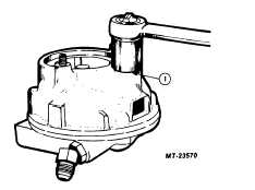
Fig. 13 Remove Valve Cap
1
Flow Control Valve Cap
5.
Loosen but do not remove flow control valve
cap, Figure 13.
6.
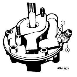
Mark position of discharge fitting in housing to
provide proper positioning during reassembly,
Figure 14. Loosen but do not remove discharge
fitting.
Fig. 14 Mark Fitting Location
1
Alignment Marks
2
Discharge Fitting
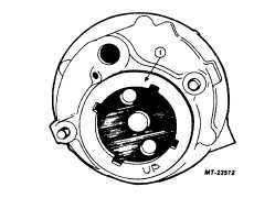
7.
Loosen but do not remove the large threaded
retaining ring in the center of the pump body
Figure 15.
Fig. 15 Ring Location
1
Threaded Retaining Ring
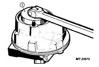
8.
Use tool SE-2838 to loosen retainer ring,
Fig. 16 Removing Retainer Ring
1
SE-2838
9.
At this point, the pump may be removed from the
vise for the remaining disassembly procedures.
10.
Remove mounting flange (gear driven pumps)
and coupling (if equipped) or mounting bracket
(belt driven pumps).
CTS-4027 - Page 13