SERVICE MANUAL
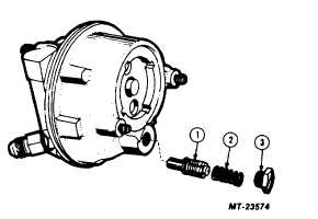
Fig. 17 Valve Components
1
Flow Control Valve
2
Spring
3
Valve Cap
11.
Remove flow control valve cap and flow control
valve components, Figure 17.
12.
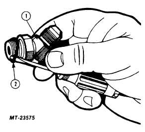
Remove discharge fitting and discard O-ring,
Figure 18.
Fig. 18 Remove O-Ring
1
Discharge Fitting
2
O-Ring
13.
Remove threaded retainer ring.
14.
Remove pump cover. Tap end of drive shaft
lightly to aid removal if necessary.
Fig. 19 Pin Location
1
Pump Cover
2
Locating Pin
IMPORTANT
Some pump housing will be drilled with two
locating pin holes. Note position of pin for
proper location during reassembly, Figure
19.
15.
Remove rear end plate and discard O-rings.
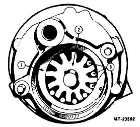
16.
Remove the shaft and carrier assembly, roll
vanes and then the cam ring, Figure 20.
Fig. 20 Remove Components
1
Cam Ring
2
Shaft and Carrier Assembly
3
Rol) Vanes
CTS-4027 - Page 14