SERVICE MANUAL
2.
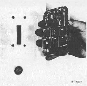
Remove three hex nuts from studs through door
from rear of handle.
3.
Remove door outer handle from door (Fig. 24).
Fig. 24. Removing Door Outer Handle
INSTALL
To install outside door handle, reverse foregoing
removal procedure.
DOOR LOCK CYLINDER ASSEMBLY
The door lock cylinder (Fig. 23) is key coded to
key switch on instrument panel so that one key operates
both. If keys are lost or a replacement of lock cylinder is
desired, see special instructions under "KEY SWITCH
AND DOOR LOCK CYLINDER REPLACEMENT".
REMOVE
1.
Remove door hardware, trim and access door
(same as for removing door glass).
2.
Disconnect rod end clip and detach control rod
from door lock cylinder assembly.
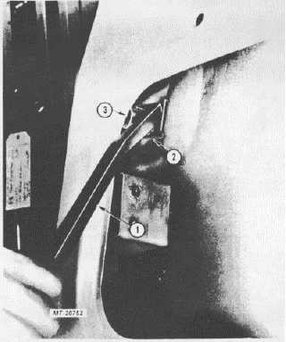
3.
Working through door access opening pry lock
retainer from lock cylinder assembly (Fig. 25)
with a small pry bar or screwdriver .
4.
Rotate lock cylinder assembly slightly and
remove from door.
Fig. 25. Removing Lock Cylinder Retainer
1.
Pry Bar
2.
Lock Cylinder Retainer
3.
Lock Cylinder Assembly
IMPORTANT
Lock cylinder retainer can be removed
without removing glass rear run channel.
Channel removed in Fig. 25 for clarity.
INSTALL
To install door lock cylinder assembly, reverse
foregoing removal procedure.
KEY SWITCH AND DOOR LOCK CYLINDER
REPLACEMENT
The instrument panel mounted key switch and
the lock cylinder in the door are coded so that one key
operates both. Code number is stamped on key switch
body just back of cap nut. Door lock cylinder assembly
does not have a code number stamped on body since
this cylinder is coded to the key switch.
CTS-4065
PRINTED IN UNITED STATES OF AMERICA
Page 16